Specifying a hydraulic cylinder without understanding force and load calculations is a bit like buying a car engine without knowing its horsepower — you might get something that runs, but it probably won’t do the job you actually need. Whether you’re designing a press, a lifting system, or a custom fabrication rig, getting the math right up front prevents underperformance, premature failure, or costly oversizing.
This guide walks through the core formulas behind hydraulic cylinder force and load capacity, along with the practical factors that affect real-world performance.
The Basic Force Formula
At its core, hydraulic force calculation relies on a simple relationship:
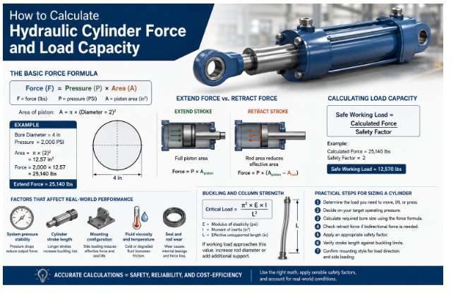
Force (F) = Pressure (P) × Area (A)
- Force is typically measured in pounds (lbs) or Newtons (N)
- Pressure is measured in PSI (pounds per square inch) or bar
- Area is the effective surface area of the piston, in square inches or square centimeters
For a standard cylinder, the piston area is calculated using the formula for the area of a circle:
Area = π × (Diameter ÷ 2)²
So if you have a cylinder with a 4-inch bore operating at 2,000 PSI, the calculation looks like this:
- Area = π × (2)² = 12.57 square inches
- Force = 2,000 PSI × 12.57 = 25,140 lbs of force (extend stroke)
Extend Force vs. Retract Force
It’s a common mistake to assume a cylinder produces the same force in both directions — it doesn’t. On the extend stroke, the full piston area is exposed to pressure. On the retract stroke, the rod itself takes up part of that area, reducing the effective surface the fluid pushes against.
Retract Force = Pressure × (Piston Area − Rod Area)
This is why cylinders are typically rated with two force values: one for extension, one for retraction. If your application requires equal force in both directions — such as certain press or clamping operations — you may need a double-rod cylinder design.
Calculating Load Capacity
Force tells you how much a cylinder can theoretically push or pull, but load capacity accounts for real-world safety margins. Engineers typically apply a safety factor — often ranging from 1.5 to 4, depending on the application’s risk profile — to account for:
- Dynamic loading (shock loads, sudden starts/stops)
- Side loading or misalignment
- Fluctuations in system pressure
- Wear over the cylinder’s service life
Safe Working Load = Calculated Force ÷ Safety Factor
For example, a cylinder generating 25,140 lbs of theoretical force with a safety factor of 2 would have a recommended safe working load of roughly 12,570 lbs.
Factors That Affect Real-World Performance
Beyond the core formula, several variables influence actual cylinder performance:
- System pressure stability — Pressure drops under load reduce actual output force.
- Cylinder stroke length — Longer strokes increase the risk of buckling under compressive loads, requiring column strength calculations (often using Euler’s buckling formula).
- Mounting configuration — Side-loaded or misaligned mounts reduce effective force and accelerate seal wear.
- Fluid viscosity and temperature — Cold or degraded fluid increases internal friction, reducing efficiency.
- Seal and rod wear — Aging components create internal leakage, lowering actual delivered force over time.
Buckling and Column Strength
For long-stroke cylinders under compressive load, force calculations alone aren’t enough — you also need to check for buckling risk. Euler’s formula estimates the critical load at which a slender column (in this case, the piston rod) will buckle:
Critical Load = (π² × E × I) ÷ (L²)
Where E is the modulus of elasticity of the rod material, I is the moment of inertia of the rod’s cross-section, and L is the effective unsupported length. If your calculated working load approaches this critical value, a larger rod diameter or additional support is necessary.
Practical Steps for Sizing a Cylinder
Determine the load you need to move, lift, or press.
- Decide on your target operating pressure based on your power unit’s capability.
- Calculate the required bore size using the force formula, solving for area.
- Check retract force requirements if bidirectional force is needed.
- Apply an appropriate safety factor for your application’s risk level.
- Verify stroke length against buckling limits for long-stroke designs.
- Confirm mounting style suits the expected load direction and any side loading.
Common Mistakes to Avoid
- Ignoring retract force when the application requires pulling as well as pushing.
- Skipping the safety factor, leading to cylinders operating at their theoretical maximum with no margin.
- Overlooking buckling risk on long-stroke, high-load compressive applications.
- Assuming rated system pressure is always available at the cylinder, without accounting for pressure drop across hoses and valves.
Why Accurate Calculations Matter
Underestimating load capacity risks premature seal failure, rod damage, or catastrophic system failure — a serious safety concern in lifting and pressing applications. Overestimating, on the other hand, leads to unnecessarily large, expensive cylinders and oversized power units. Precise calculation strikes the balance between safety and cost-efficiency.
If you’re specifying cylinders for an industrial project, working with an experienced manufacturer can help validate your calculations against real-world performance data. You can know more about industrial hydraulic equipment options, or explore a dedicated range of hydraulic cylinders engineered for demanding load and pressure requirements.
Conclusion
Calculating hydraulic cylinder force and load capacity isn’t just an academic exercise — it’s the foundation of a safe, efficient, and cost-effective hydraulic system. By understanding the relationship between pressure, area, and force, accounting for retract-stroke differences, applying sensible safety factors, and checking for buckling risk on long strokes, engineers can specify cylinders that perform reliably for years rather than failing prematurely under real-world conditions.